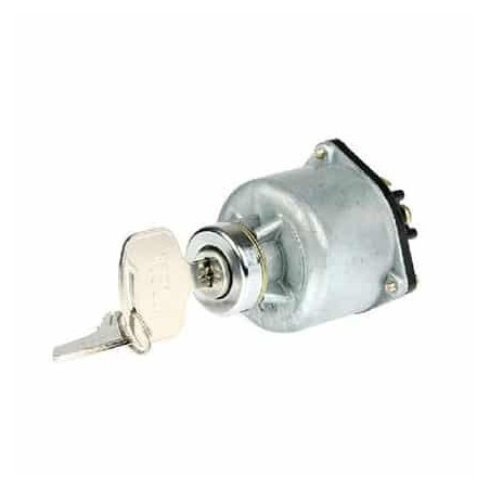
| Features |
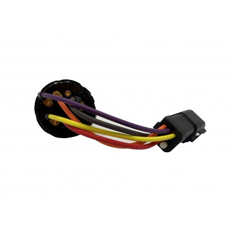
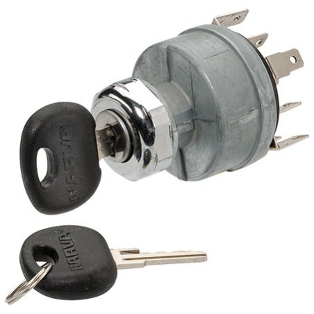
• B1 and B2 are linked (with linking connection supplied) and are to be supplied with a 'battery feed'
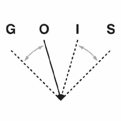
• G1 and G2 are linked (with linking connection supplied) and will supply power to the 'glow' circuit when the switch is activated.
• M is the 'ignition' output from the switch
• S is the 'start wire output' from the switch |